Looking forward to make your first robotics project? Then a basic line follower robot is the thing for you. Line follower is a machine that follows a line, either a black line on white surface or vise-versa. For Beginners it is usually their first robot to build and show. In this tutorial, we will teach you to make the line follower robot move on the line with a type of feedback mechanism. It’s the most basic example of adding small intelligence to a robot, but it’s actually the designer’s intelligence!!
After reading this section completely you will be playing with the one shown below. Moreover we will make it simple and one that can be easily modified in future. Believe me a line follower is one of the most coolest and easy to build robot as your first project.
The main electronics/mechanical components that will be used in making this line follower robot are two or five sensors made using LDRs (like IR sensors), transistors as motor driver circuit (L293 motor driver IC), General purpose board, Two DC motors and battery.
Now lets get started to make line follower you have seen in the video.
Chassis
The very first component needed in a line follower is a chassis which hosts the entire components and acts as a body of your bot.It’s basically the frame of the robot on which motors and wheels are mounted and all the circuitry part is also placed on it. It is easily available in the market and that to at a very cheap rate.
Drive Mechanism
We will be using a three wheel differential drive using two motors and one caster wheel or an Omni directional wheel. The Direction and speed of the two motors can be controlled independently using motor driver IC which contains H-Bridge to drive the motor in both the directions.
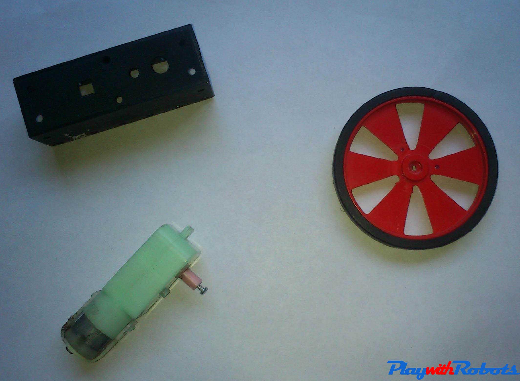

Our first step would be fixing the motors to the chassis with a screw.
Now fix motors, caster and also attach wheels to the motors.
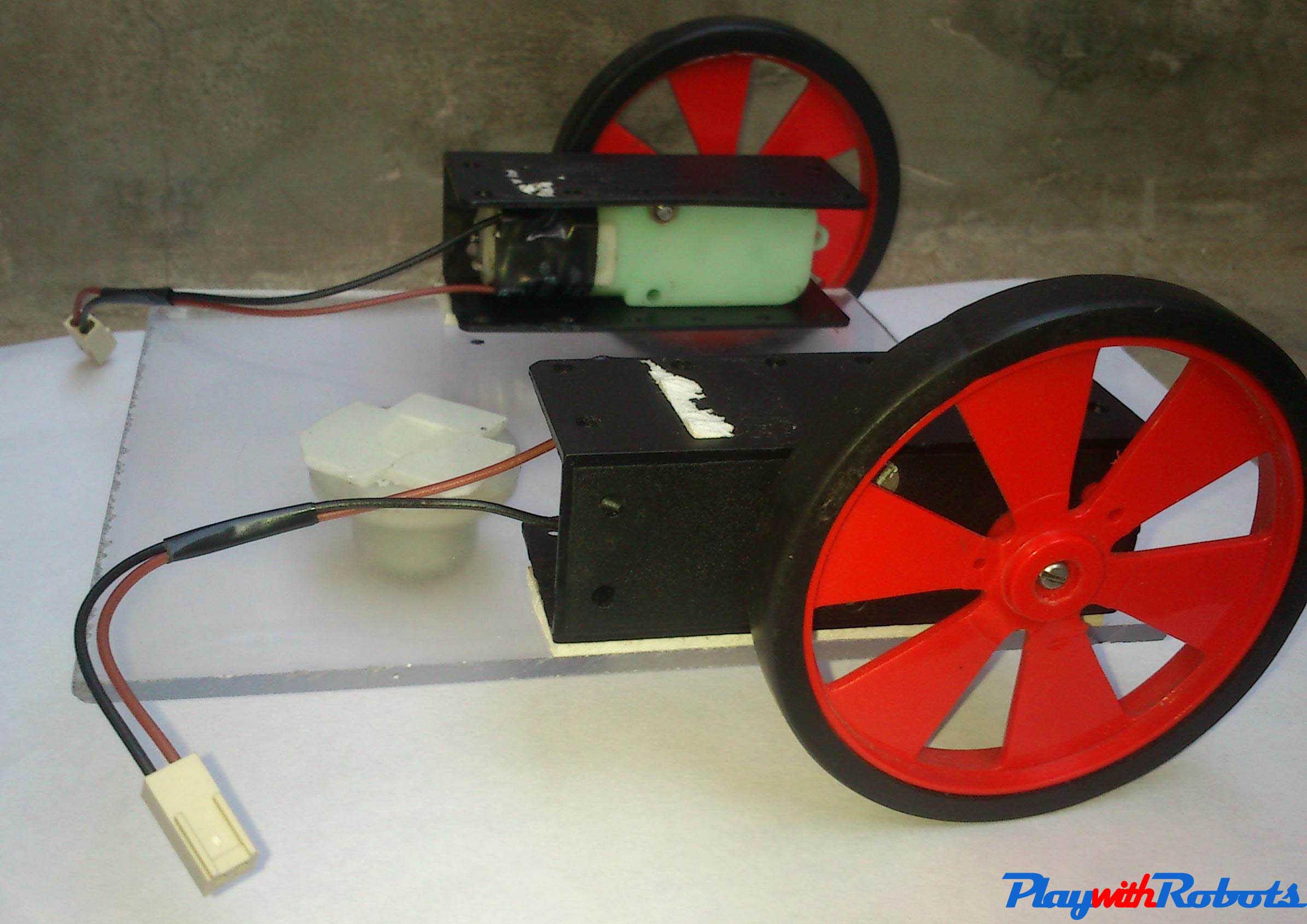
Final chassis
Now its time to attach L293 motor driver IC and the ir sensors!.
The IR sensor array consists of individual IR LEDs and IR photodiodes. The IR light emitted by the LED strikes the surface and is reflected back to the IR photodiode. The photodiode then gives an output voltage proportional to the reflectance of the surface (high value for light surface and low for black/dark surface).

Now the connections you have to make can be followed from the image below.

You can avoid the resistor used in the circuit. After clearly following the connections and mounting all the components your line follower is physically ready. The only and most important thing to do is getting your line follower mentally ready. Yes, you need to provide instructions to your line follower to follow instructions. If you are good at coding i would suggest you to try forming the code for line follower yourself by checking out the logic below. In case you are unable to form the code get it from the end of article.
LOGIC OVERVIEW
The line following robot is programmed to basically avoid the color black. If both sensors see black, then the robot will back up until it no longer sees black. If one sensor sees black, then the robot will turn in the direction of that sensor until it no longer sees black. Other than that, if the robot doesn’t see black on either sensor, it will simply move for- ward. In this application, the black line is created using common electrical tape. The logic for this algorithm is shown below along with a graphical representation of the front of the line following bot for reference. 
Now , use Arduino software to get your code loaded to the bots memory. In case you dont have a software download it from here https://www.arduino.cc/ . Copy and Paste the code given below in case you are unable to formulate your own.
void setup()
{
pinMode(13,OUTPUT);
pinMode(12,OUTPUT);
pinMode(11,OUTPUT);
pinMode(10,OUTPUT);
pinMode(4,OUTPUT);
pinMode(5,OUTPUT);
}
void loop()
{
int left=digitalRead(4);
int right=digitalRead(5);
if(left==HIGH && right==HIGH)
{
digitalWrite(13,HIGH);
digitalWrite(12,LOW);
digitalWrite(11,HIGH);
digitalWrite(10,LOW);
}
if(left==HIGH && right==LOW)
{
digitalWrite(13,HIGH);
digitalWrite(12,LOW);
digitalWrite(11,HIGH);
digitalWrite(10,HIGH);
}
if(left==LOW && right==HIGH)
{
digitalWrite(13,HIGH);
digitalWrite(12,HIGH);
digitalWrite(11,HIGH);
digitalWrite(10,LOW);
}
if(left==LOW && right==LOW)
{
digitalWrite(13,HIGH);
digitalWrite(12,HIGH);
digitalWrite(11,HIGH);
digitalWrite(10,HIGH);
}
}
After compiling and uploading the code to your bot its time to test your hard-work. So, form a track with a black colored tape and let your line follower bot do the action. Let me know the outcome you got and in case of any trouble feel free to get it sorted by mentioning the problem you are facing in the comment below.
For any Suggestion or query reach me at- rahulshahi.1995@gmail.com
Have fun roboting!


